Clariant Power System Ltd.

When Two Transformer Incomers Have Different Power Quality Problems.

Power quality case study · Cement manufacturing

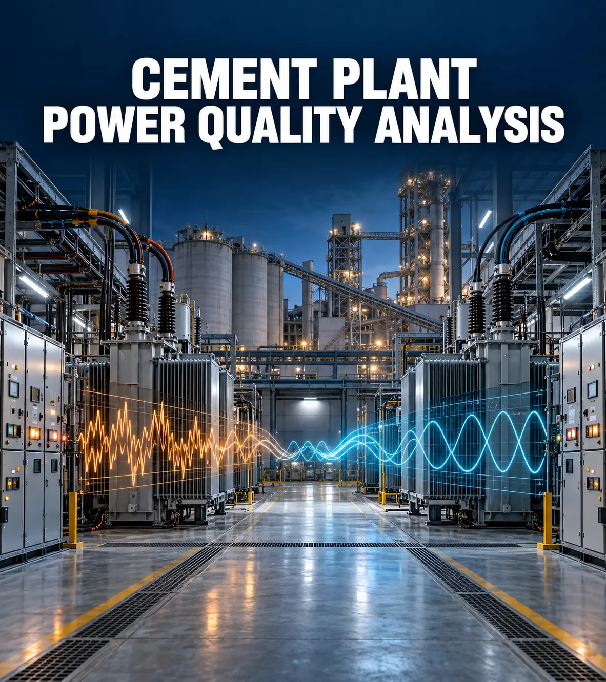
When Two Transformer Incomers Have Different Power Quality Problems.

IndustryCement Manufacturing
ApplicationIndustrial Power Distribution
SolutionRTPFC + Active Harmonic Filter

A cement manufacturing plant was experiencing low power factor and harmonic distortion at two transformer incomers.

At first, the requirement seemed straightforward: improve the plant's electrical performance.

But there was an important question to answer first:

Were both transformers actually facing the same problem?

Clariant Power set out to find that out.

It Started With the Measurements

Clariant Power conducted a detailed Power Quality Analysis using a Fluke Power Quality Analyzer at both transformer incomers.

The study measured key electrical parameters including power factor, current, VTHD and ATDD.

The results showed that the two incomers had noticeably different conditions.

Transformer 1

Power factor0.85
ATDD7.2%

At Transformer 1, the power factor was 0.85, with ATDD at 7.2%.

Transformer 2

Power factor0.77
ATDD35.3%

At Transformer 2, the power factor was lower at 0.77, while ATDD reached 35.3%.

That difference was important.

It meant that simply applying the same corrective configuration to both transformers would not address the actual requirement.

The Measurements Shaped the Engineering

Based on the conditions identified during the analysis, Clariant Power configured the solution for each transformer.

Transformer 1

715 kVAr, 525 V RTPFC Panel

The RTPFC panel was configured to address the power-factor requirement identified at the incomer.

Transformer 2

715 kVAr, 525 V RTPFC Panel + 200 A + 300 A Active Harmonic Filter

Here, the significantly higher harmonic distortion called for additional harmonic mitigation alongside power-factor correction.

The solution was therefore not based on a standard configuration.

It was based on what the measurements showed.

Then We Measured Again

After implementation, the electrical parameters were measured again to verify the improvement.

Results

ParameterTransformer 1Transformer 2
Power Factor0.85 → 0.990.77 → 0.99
Current1432 A → 1221 A1034 A → 800 A
VTHD2.5% → 1.9%5.4% → 4.2%
ATDD7.2% → 5.9%35.3% → 7.4%

The most significant improvement was seen at Transformer 2.
Its power factor improved from 0.77 to 0.99, while current harmonic distortion reduced from 35.3% to 7.4%.
Across both transformer incomers, the case study reports that voltage and current harmonic distortion were brought within IEEE-519 limits after implementation.

One Plant. Two Conditions. One Measurement Led Approach.

This project shows why power-quality correction cannot always be approached with a one size fits all configuration.

The two transformer incomers were part of the same plant, but their electrical conditions were different.

Clariant Power's approach was simple:

  1. Measure the condition.
  2. Understand the requirement.
  3. Engineer the solution.
  4. Measure the result.
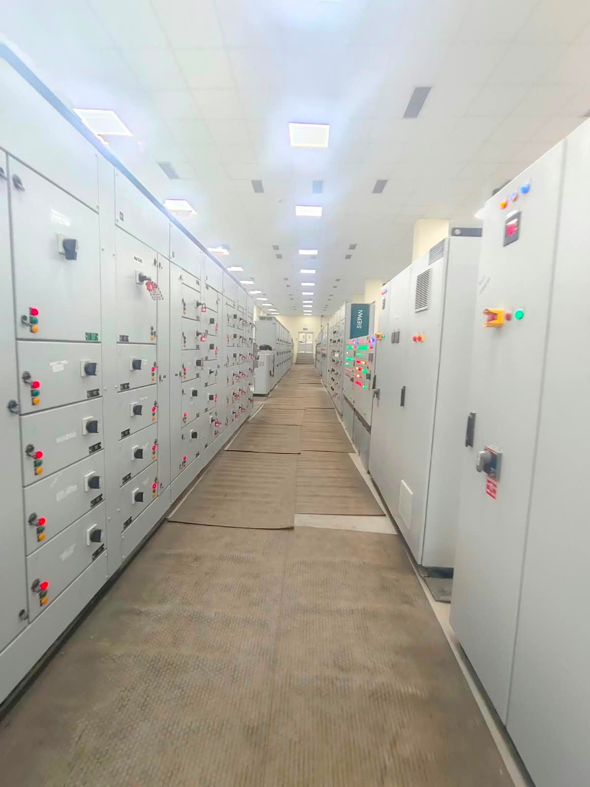
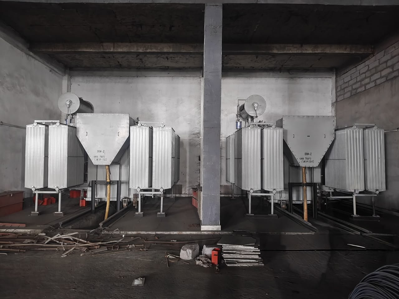
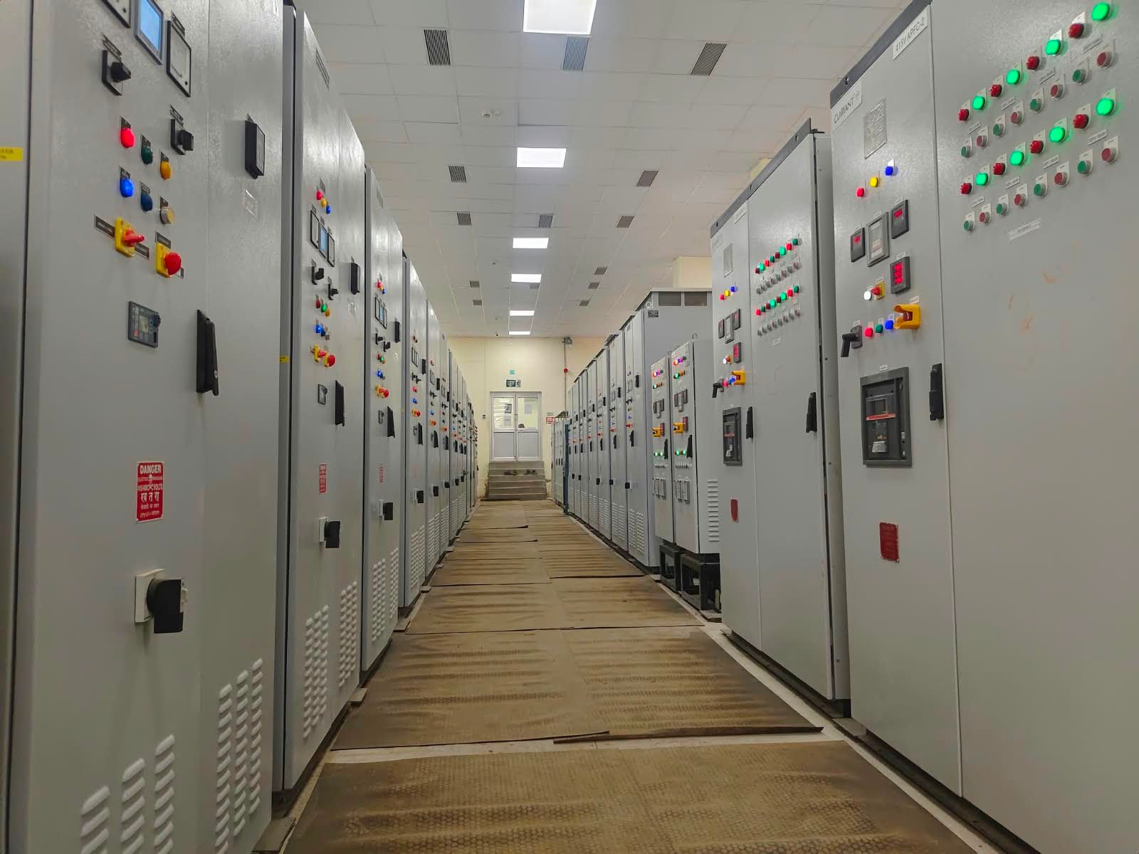
Clariant Power industrial installation

Project Snapshot

Industry

Cement Manufacturing

Application

Transformer Incomers

Solution

RTPFC + Active Harmonic Filter

Power Factor

Up to 0.99

ATDD at Transformer 2

35.3% → 7.4%

Facing a similar power quality requirement?

Talk to Clariant Power's engineering team.

Contact Engineering Team

It's all about saving your money!

+91-20-67332999

sales@clariantindia.co.in

799/A, Clariant House, Abhijeet Court, Bhandarkar Road,
Pune-411004.

Monday-Saturday: 10am –  7pm

© Clariant Power System Ltd. 2024, All Rights Reserved.